Q:

The T.U.R.D Coming !

Just a pic of the Tactical Utilitran Rifle Design striaght from the Voleworks design dept. This is what ive come up with …. 😕

Its .177 , 15 round mag , collapsible stock , AR grip , pump action , shrouded , 70 shot regulated and at 70cm long.
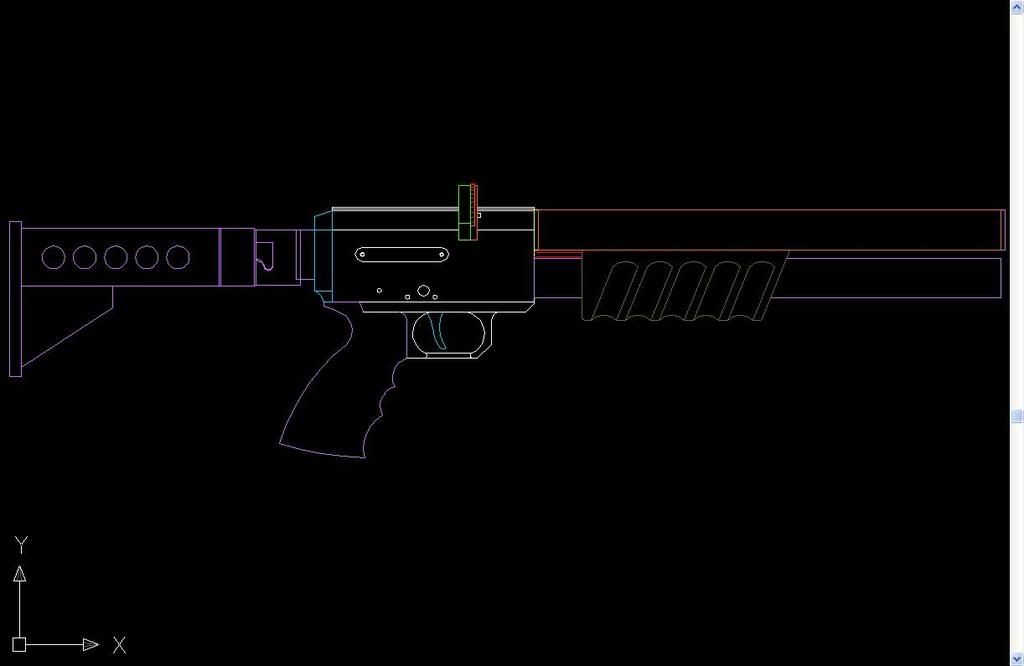
I wanted to design a gun for the guys who do ” Ratting ” as its known over here ,so its a small take down type gun to shoot rats in barns. If i get the drawings finished in the next couple of weeks the first prototype should start soon arfter on my mates new CNC machining centers .
Ive been drawing on Auto CAD for weeks , and im now experiencing the joys of learning 3D CAD ( for this and my CNC mill).
So i thought id see what you guys like / dislike because its not going to be for sale in the USA …hehe !. 😀
So what do you think !
L8r all 😀

Mods/Machinists

All Replies

Viewing 15 replies - 106 through 120 (of 185 total)

1 2 3 7 8 9 11 12 13

Finished the breach with a few angles on the side , think that all im going to do , just makes it look slimmer. The trigger group drilled but ive got to finish the safety slot next to complete. Stock attachment made as well as the pump action slide and hammer so on to the slide locking catch and safety catch. 😀 . Im just putting off making the probe as its going to be a pain 😯 .

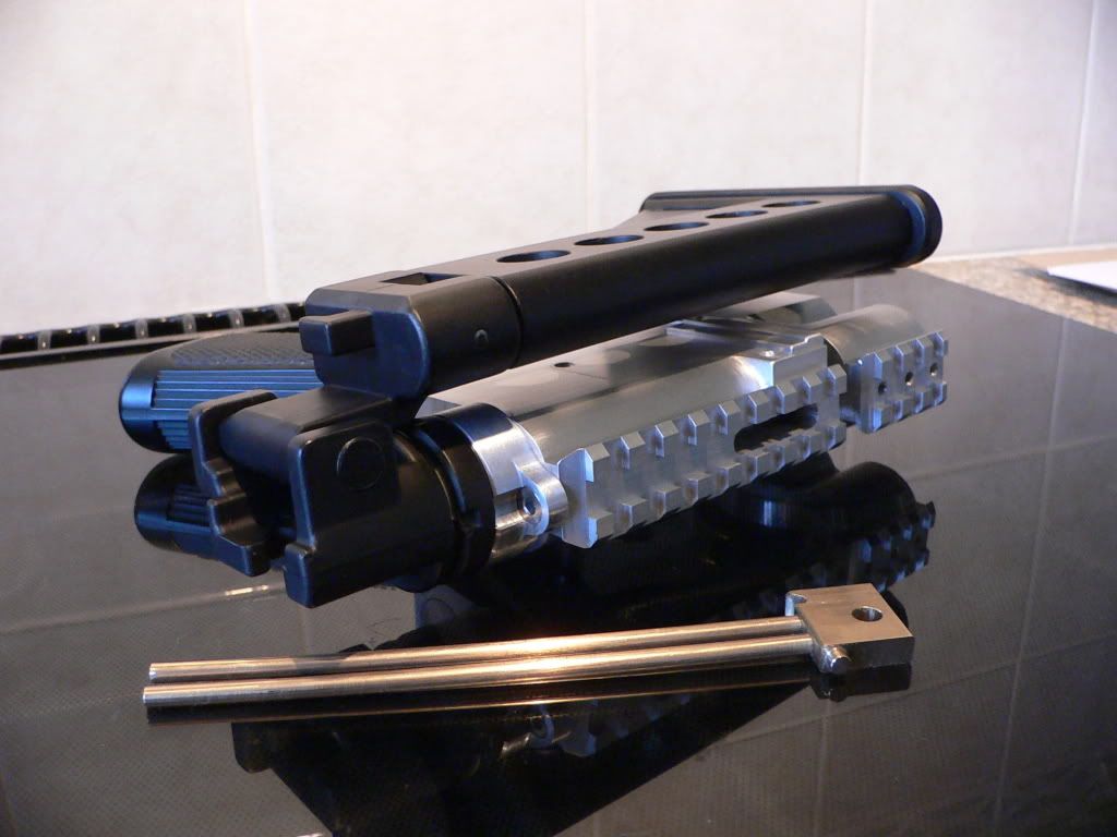
Got to machine the stock as it dosnt lock in a straight line ,slightly off center but its only a cheap Evilbay item.
I was looking at making the shroud out of carbon fiber tube but its too dam expensive so thin wall alloy tube will have to do and its the only bit of metal im hoping il have to buy 😕 .
L8r all 😀

nice job ,looks very clean and acurate metalwork.
Congratulations and go to the next stage.
Bye
Pd:excuse my tarzan-style english

very nice!

No more Russian guns just UK from now on LoL 😀
Trigger group part done and im now starting on wasting away as much metal from the breach as possiable. Ive got to fix the trigger group to the breach before i can mill some more off the sides. Im aiming to not have a slab sided gun like the T4 , how it will look arfter im finished ? ….time will tell. With a CNC it would look alot more unifrom / flowing but ive only got ball cutters and needle files. Im not sure about it at the moment but its too late now , hopefully shotblasting will soften the edges and blend it better 😕 .


Waiting for screws to arrive so can start again 😀
L8r all 😀

quote WalkonKing:

Air Arms needs to hire you and have you start making all those Russian guns for them 😀

Seriously…

Air Arms needs to hire you and have you start making all those Russian guns for them 😀

Ive got a copy of Buckley,s book which gose into some depth about O-rings on valves , which he states the way of putting the O-rings before the thread as you say R2D2 . I agree with you and this would have been the way i would have liked to have made my valves but the cylinder tubes i got form Baz / Sean have quite a deep thread therefore the valve would be overly long. I cant machine the tubes as there too long for my machine so the O-ring had to go behind the thread. This isnt a problem as if you look at FX / Logan , AA S200 to name a few, they all fit the O- ring behind the thread. I think Sean machined the tubes for a Logan valve ( which Baz lent me ), so if i stick to that valve design it should work 😀

Side plate for the indexing mech done

Finished the probe and hammer bore caps , now working on the probe locking catch and stock fitting.

Buba,

I have just been looking trough the pictures of your design.

When designing pressure equipment it is very important NEVER to put pressure on the threads in your reservoir.

For your own safety put the o-ring before the threads when plugging your reservoir.

You can see the right design in the book “The modern pneumatic airgun” by H. M. Buckley.

If you have questions please feel free to contact me.

Best Regards
Jakob

buba – you never cease to amaze me !

WOW that is gonna be SICK! To bad we can’t get that here in the states! I would love one of those for Plinking crows and rats also….

I got a little drool in the corner of my mouth…

you got big imagination! keep it up mate!

So nearly finished the breach but ive made a few F***k ups along the way 😯 . First can anyone tell me if the top slot on the weaver rail has to be 3mm deep as ive managed to do mine 2.3mm ( dont ask !!! how ) , im just wondering if a weaver scope rings will still sit on the rail or not . Its why i havent cut the top 45 deg,s incase ive got to mill it all again. The second prob was the pump push rod holes , ones nice and square and the other wandered by .5mm …..damit 🙁 . This is the one reson i didnt want to make this as my mill wouldnt go high enough to peck drill the dam holes. So im just going to have to file out the hole square once ive got some 4mm rod to check alignment

I realy dont want to mill the rail again 😕
L8r all

The pin from the cocking probe that you see above cocks the hammer when you pump. The hammer has a slot in the top that the probe pin rides in to stop the hammer turnning in the hammer bore and for the pin to move the hammer far enough back to lock the hammer on the hammer shear.
😀

I see, – How does it come in contact wit the hammer??

Well ………It would cock and lock like the T4. When you cock the dark grey center moves back by 2mm allowing three 3mm bearings to fall down onto the 50 deg suface clearing the probe bore. To hold the probe back while say you replace the mag theres a latch on the side of the gun that holds the pump side bar ( brass bit that the pump rods go into ! ) in place. When you pump forwards the bearings fall into a groove in the probe bore and are locked into positon when the center dark grey bit of the probe returns into flush position with the lighter grey outside of the probe helped by a 3lb spring in the probe bore. There clear as mud ! 😯


By the way ive started building the breach but il only post pics when ive finished parts , il be some time me thinks !
L8r all 😀

Viewing 15 replies - 106 through 120 (of 185 total)

1 2 3 7 8 9 11 12 13
  • You must be logged in to reply to this topic.